SwatEd Viewport Controls
By default the editor has four viewports, three of them show an orthographic view, and the fourth being a 3D view of your map close to how it would be seen in-game.
The viewports can be moved around no matter what tool you currently have selected, because the tools only take affect when you hold down ctrl or shift. For the purposes of this tutorial it will be assumed that the viewport moves around the map.
| Orthographic Views | |
| Controls | Action |
| Left-Mouse Button + Move Mouse Right-Mouse Button + Move Mouse | Moves the viewport in the same direction as the mouse movement. |
| Left-Mouse Button + Right-Mouse Button + Move Mouse Up/Down | Causes the viewport to zoom in or out depending on the mouse direction. |
| 3D Perspective View | |
| Controls | Action |
| Left-Mouse Button + Move Mouse Up/Down | Causes the view to move parallel to the X plane. |
| Left-Mouse Button + Move Mouse Left/Right Right-Mouse Button + Move Mouse Left/Right | This changes the yaw (Rotates around the Z-axis). |
| Right-Mouse Button + Move Mouse Up/Down | Alters the pitch of the current view. |
| Left-Mouse Button + Right-Mouse Button + Move Mouse Up/Down | The moves the view parallel to the Z-axis ('Strafes' up and down). |
| Left-Mouse Button + Right-Mouse Button + Move Mouse Left/Right | The moves the view perpendicular to the Z-axis ('Strafes' left and right). |
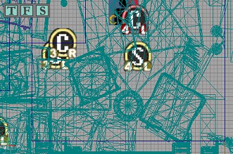
All of the viewports have a set of axes in the lower left-hand corner, these show the three planes; X, Y, and Z, and their direction. The direction of a particular axis is determined by starting from the point at which all three axes meet (Negative infinity), and moving too any point higher than the origin along the desired plane. Viewing these axes is most useful when using the 3D viewport as a reference to manipulate brushes or actors.

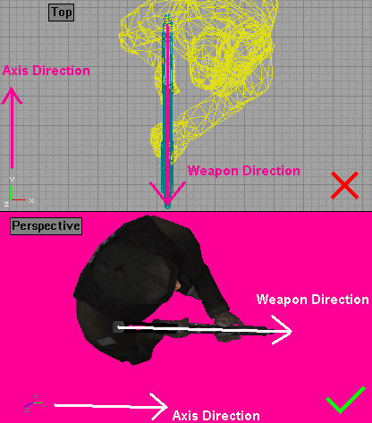
It is important to remember that the axes directions shown in the top viewport are incorrect. The Unreal Engine uses a left-handed coordinate system, but because the orthographic views always depicted the axes in an "L-Shape", the top viewport shows the axes using a right-handed coordinate system. This is better explained using the image below (Note: Image has been edited to fit on the page).
I have positioned the weapon so that its muzzle points straight along the Y-axis. However in the top view the weapon's muzzle is pointing in the opposite direction to the Y-axis. These axes are incorrect. The same weapon seen from the perspective view shows its muzzle is pointing in the same direction as the Y-axis. These axes are correct.
It is possible to customise the configuration of the viewports; you can change both the position and size of each view port.
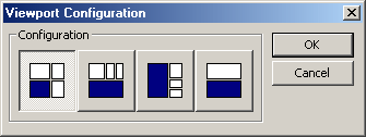
There are a selection of preset configurations available that can be accessed by the View drop down menu. If you go to View > Viewports > Configuration it will display a dialog box shown below, the layout of the viewports is shown on each button with the perspective view highlighted in blue.
You can also create custom configurations, either completely new layouts or by simply modifying the existing ones. This is also done using the View drop down menu, select View > Viewports > Floating, this unlocks the viewports and each view becomes a separate window.
Now you can resize and position the viewports however you like, you can also add and remove viewports. To add a viewport select View > Viewports > New Viewport, to remove a viewport simply close it using the standard Windows procedure.
To prevent the viewports from being unintentionally altered you can lock them into place by selecting View > Viewports > Fixed.
After changing your viewport configuration you may receive the following error at start-up: "Can't find 'ini:Engine.Engine.ViewportManager' in configuration file". To fix this delete the SwatEd.ini file from your \SWAT 4\Content\System directory, this will reset any changes you have made.
All of the viewports have a small toolbar located above the rendered view. It features a label to remind you of the viewports current mode, and also a number of buttons to change the display mode; these are explained in section 5. Viewport Display Modes. The remaining buttons are explained here.
| Real-time Preview: This toggles whether a viewport will render a dynamic or static scene; by default it is turned off thus displaying a static scene. When turned on the viewport is constantly refreshed allowing you do see moving parts of your map in action, such as dynamic lights. Also when enabled it allows you to see the updated locations of brushes and actors as you change them in other viewports, a static scene would need to be manually refreshed before these changes will become visible. |
| Lock to Selected Actor: When this is enabled it will centre you view onto the origin of any actor of brush you select, this is very useful to locate objects in the 2D views by selecting them in the 3D view. |
 | Show Large Vertices: This causes the vertices of selected brushes or meshes to appear larger than normal. This is helpful when you are attempting to manipulate the vertices of a brush. You cannot alter the position of vertices for a mesh, however right-clicking a vertex will snap it to the grid which is useful for aligning meshes. |
You can also right-click on this tool bar to change these options through a pop-up menu. It also contains a View menu that will allow you to show or hide different objects from the editors view of your map.
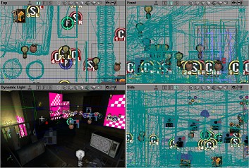
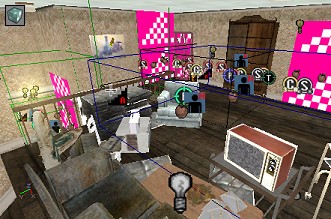
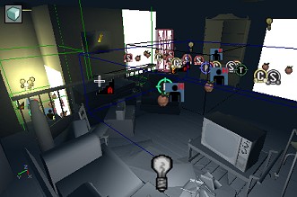
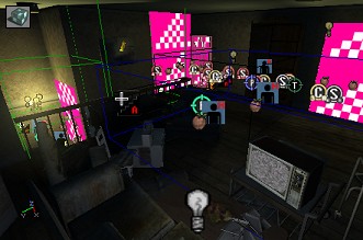
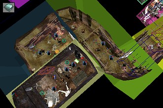
Viewports can be set to render in a number of different modes, there are three orthographic views and eight three-dimensional (3D) views, all have their uses once you begin to construct different parts of you map.
There are three orthographic views available, one for each plane (X, Y, and Z). These views are referred to as: Top looking down the Z-axis, Front looking down the Y-axis, and Side looking down the X-axis. While viewing a single object from all three views they allow you to have a 3D perception of that object.
 This 3D view renders all of the geometry and meshes in wireframe, only the edges of the polygons are rendered. This is most useful to manipulate BSP geometry, and all of the brushes retain the same colours as in the 2D views making it easier to find the desired area.
 All of the textures applied to BSP geometry are rendered in flat colours; any geometry that has the same texture will be rendered in the same colour. This allows you to find areas that contain a large number of textures that may decrease performance. All actors including Static Meshes are rendered as normal. Also no lighting is rendered.
 Apparently this should render your map outlining where the engine has created BSP cuts. BSP geometry is rendered in basic colours with different shades representing where cuts have been made. However it just looks white to me. Note: If you switch to the perspective (Wireframe) view and then toggle the Real-time Preview on / off; the BSP cuts will become visible.
 This view renders everything normally except it does not apply any lighting effects. This is useful to see what you're doing when trying to align textures properly. However the texture's appearance is likely to change once the lighting has been rendered as well.
 All geometry, including actors, are rendered purely based on the amount of light that falls upon it. They are rendered as varying shades of black to the light's colour, the brighter the colour the more light is shining there. This mode is useful to either create exact shadows or to check the amount of lighting in an area, as textures will often distort this.
 This view is rendered as the closest to what would be rendered in-game. It features all of the geometry correctly rendered and with lighting effects applied to it. The main difference is that actors that are not normally rendered in-game are still visible. Although this view is lablled as 'Dynamic Light', you will not be able to see these unless Real-time Preview has been enabled.
 The Zone/Portal mode renders each zone's BSP geometry in a different colour; it also shows where BSP cuts have been made within each zone. This is very useful to make sure you have all your zones are completely separated from each other. Zones provide the engine with a very fast way to ignore geometry that doesn't need to be rendered.
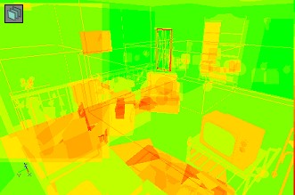
 It is easy to be mislead by the name, however this mode actually represents the number of passes required to correctly render the current view. The colours range from green to red, green meaning only a single pass is required, orange areas need a few passes, and red are considered to require too many passes. Large areas of red may cause a huge decrease in performance and should be adjusted accordingly.